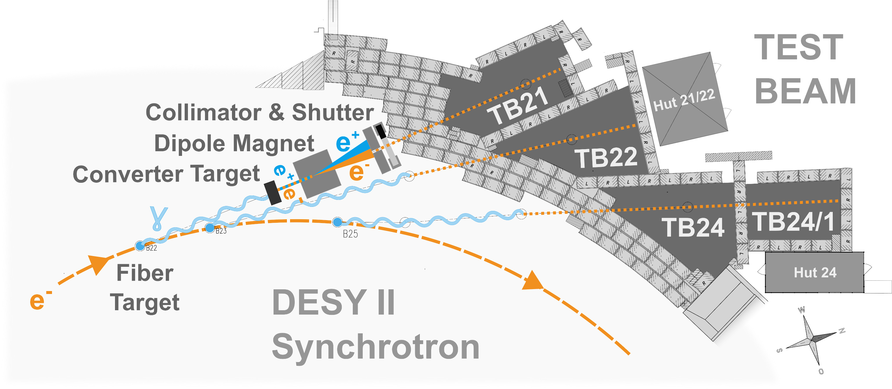
Schematic layout of the beam generation at the DESY test beam
Introduction
The counting rooms for test beams TB24 and TB21/22 are close to the areas. The entire control system for each area is located in these huts. There is space for electronics and data acquisition, but it is also possible to place it in the area. The huts have 1 Gbit and wireless Ethernet connections and there are RJ45, optical fiber and BNC and HV patch panel connections to the areas. Cycle trigger and bunch trigger signals from the accelerator are also available in the huts.
Internal users can just bring their computers, and external users will be in the DESY guest network.
The beam areas are surrounded by shielding blocks and are equipped such that flammable gases could be used in the test beam areas. (All sorts of gas -also premixed- can be supplied by the DESY gas group MEA6. The use of flammable gas or other hazard materials needs special precautions. Please discuss this well before your test beam.)
The areas can be equipped with translation stages. The large ones can carry up to 1000 kg, the smaller ones can take 30 kg
Beam Generation
A bremsstrahlung beam is generated by a carbon fiber in the circulating beam of the electron/positron synchrotron DESY II. The produced photons are converted to electron/positron pairs via a metal plate target (converter). Then the beam is spread out into a horizontal fan using a dipole magnet. Like a slice, the final beam is cut out of this fan with a collimator.
The underlying physics is simple. The bremsstrahlung spectrum has a 1/E dependence. The energy distribution of the electron/positron pair production is nearly flat, the geometry is fixed by the beam pipe. By setting the dipole magnet current, the resulting beam momentum after the collimator can be choosen. The real situation is little more complicated because the energy of the synchrotron varies with time, i.e. the bremsstrahlung edge of the photon spectrum changes in time with cycles of the accelerator. Obviously, the beam particles can only be produced when the accelerator energy/c is above the chosen momentum.
Parameters
The carbon fibre has a thickness of 7 µm. About 10 of these fibres are prepared inside the fibre holder on a fork. By moving this fork in and out of the beam, a broken fibre can be replaced without opening the machine vacuum.
The photon beam leaves the DESY II vacuum chamber through a 0.5 mm Aluminium window and then it has to pass through the DESY III vacuum chamber via two 0.5 mm Aluminium windows. The beam 24 is converted before DESY III.
The geometric arrangement is such that for beam 21 and 22 a bend of 32 mrad and for 24 a bend of 80.6 mrad and a second bend of 32 mrad backward is needed to get the beam through the centre of the collimator (see detailed layout and complete hall).

Target station for TB22 |
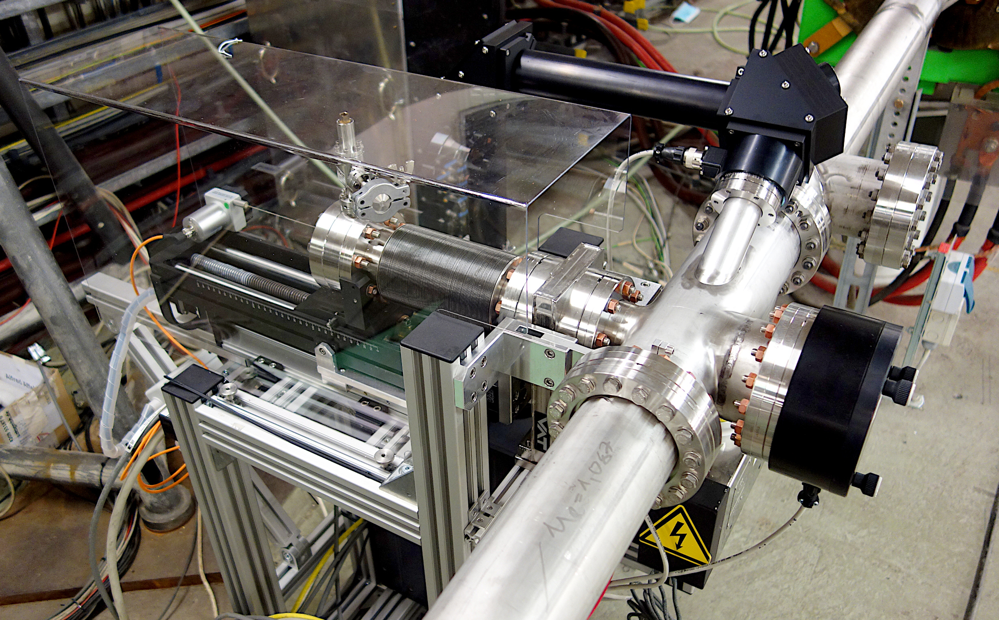
Close view of target station and mover |
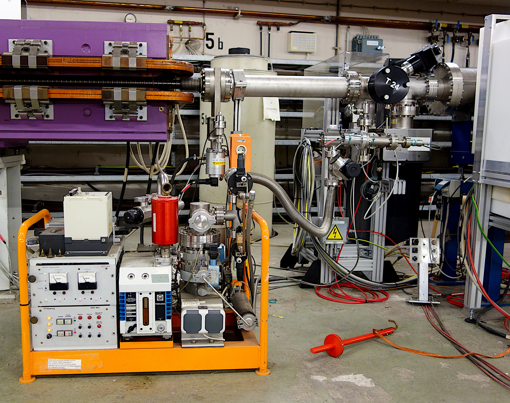
Target station for TB24 with connected vacuum pump |

3D model of target station including cabinet for camera to check the fiber |
3D model of fork with carbon fibers in the primary target station |
Converter TargetFor the conversion from photons to electron/positron pairs, there are different converter targets available made of a Cu wire or Al and Cu plates of different thickness from 1 mm to 10 mm. Which target is selected is controlled via a homemade NIM module (list of currently installed converters). |
No: 1 | Low [14KB, 300x215] | High [174KB, 1703x1011]

Converter-target station at beam line 24
No: 2 | Low [10KB, 99x215] | High [1.2 MB, 1308x2048]

Secondary-target control NIM-module
|
|
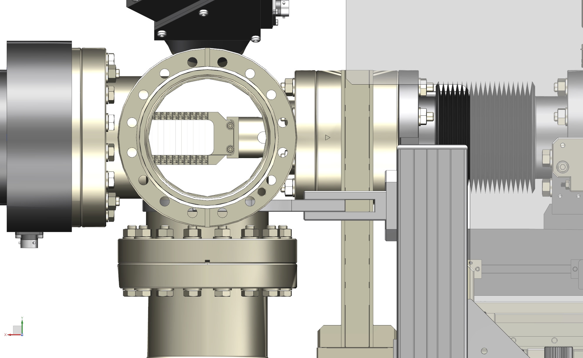
Moveable Collimator
The four collimator jaws have their own control box. The beam shutter and the shielding wall follow the variable collimator behind the magnet.
No: 1 | Low [13KB, 300x181] | High [104KB, 1127x637]
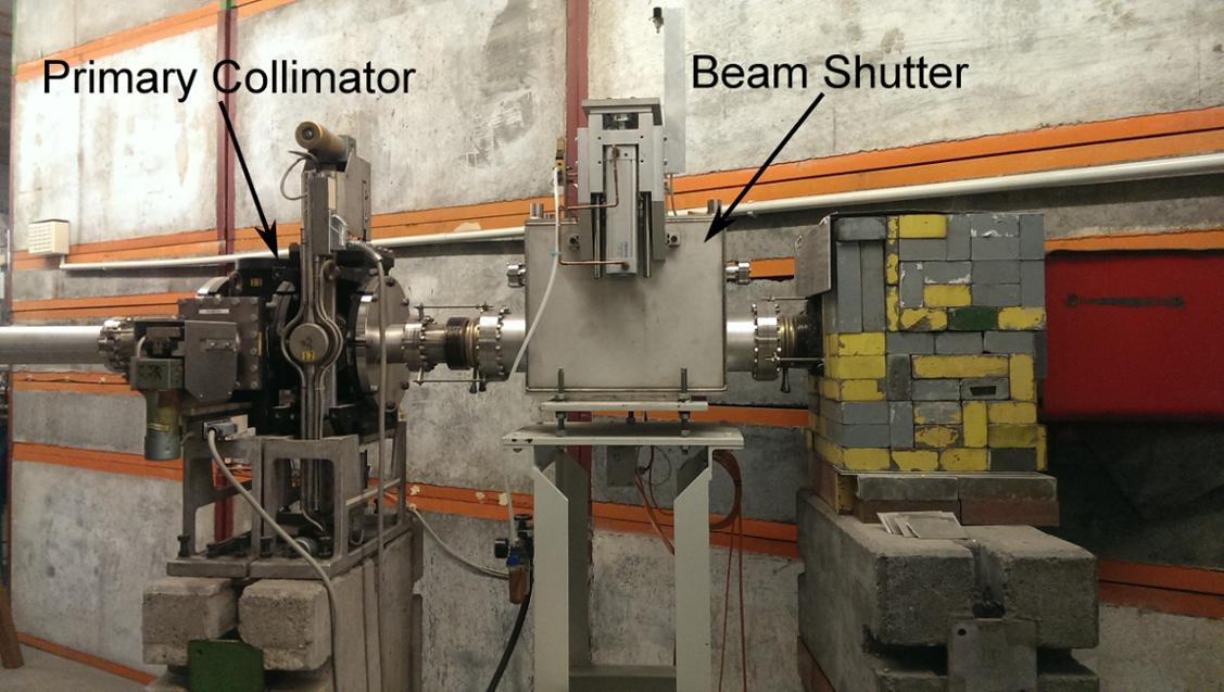
Primary collimator and beam shutter
No: 2 | Low [13KB, 195x181] | High [1.2 MB, 2048x1311]
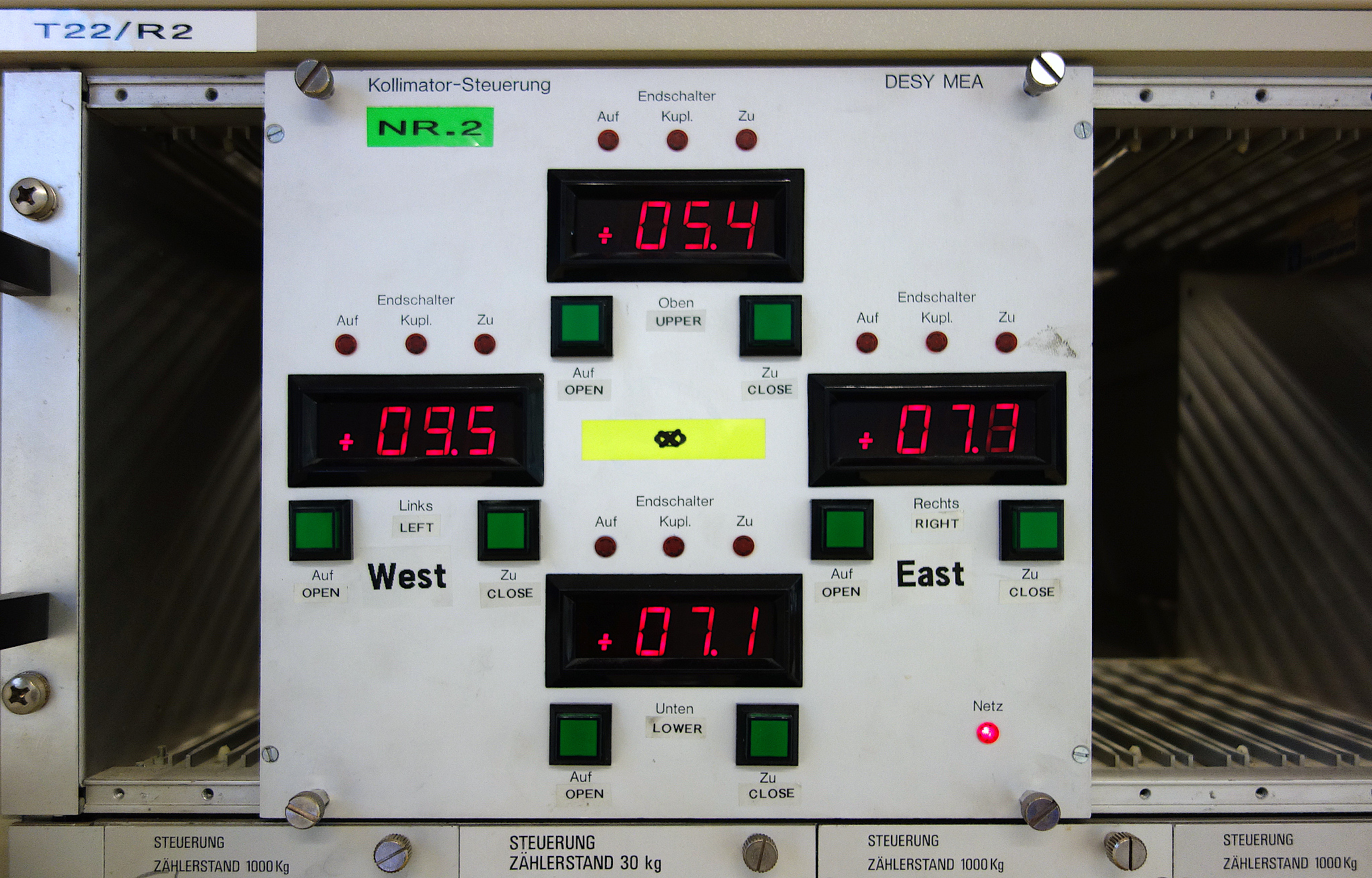
Collimator control in the user hut
Lead Collimator
Inside test beam areas, it is possible to put a second lead collimator. It has exchangeable inserts. Several inserts with different apertures are available. This auxiliary collimator catches particles scattered off the yaws of the main collimator. Its opening should be bigger than the one of the main collimator.
Directly before the secondary collimators, beam monitors are mounted at all beam lines. Their signal is fed into the accelerator control system and are displayed inside the user huts.
No: 1 | Low [69KB, 245x280] | High [1.0 MB, 1710x1952]
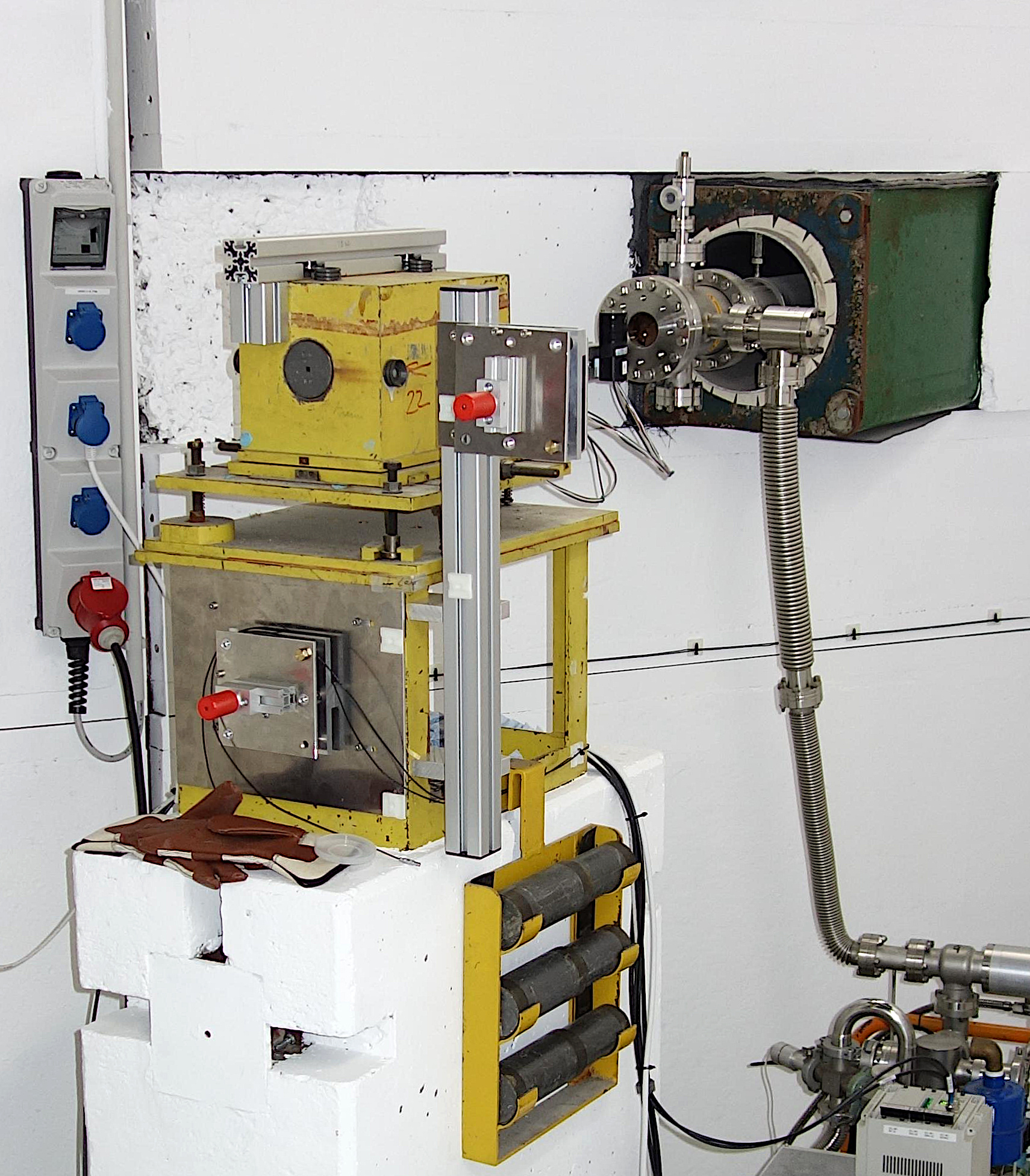
Secondary collimator (yellow) including exchangeable lead inserts inside the beam area
No: 2 | Low [23KB, 382x280] | High [1.0 MB, 2048x1221]
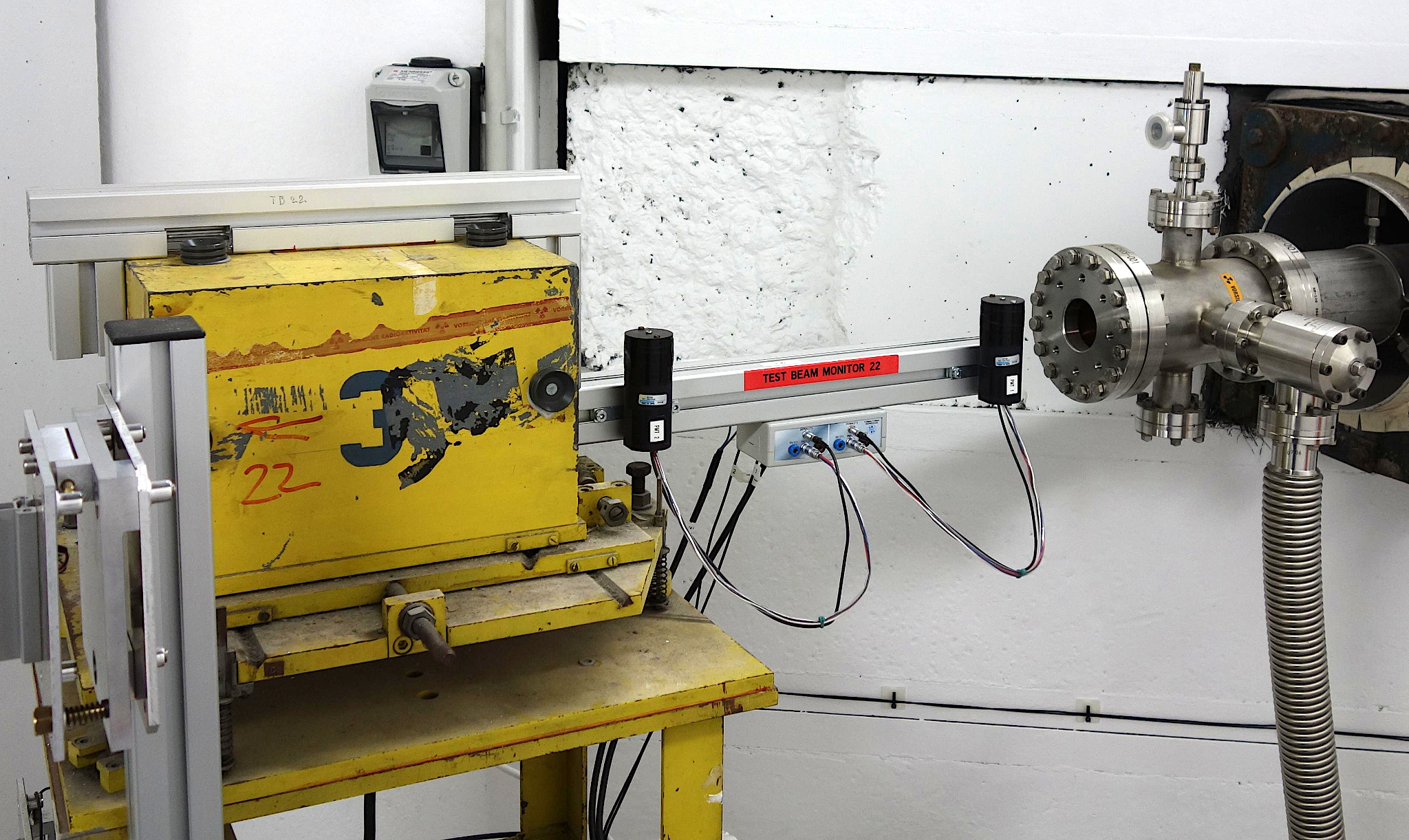
Beam monitor between vacuum pipe and secondary collimator
|
|
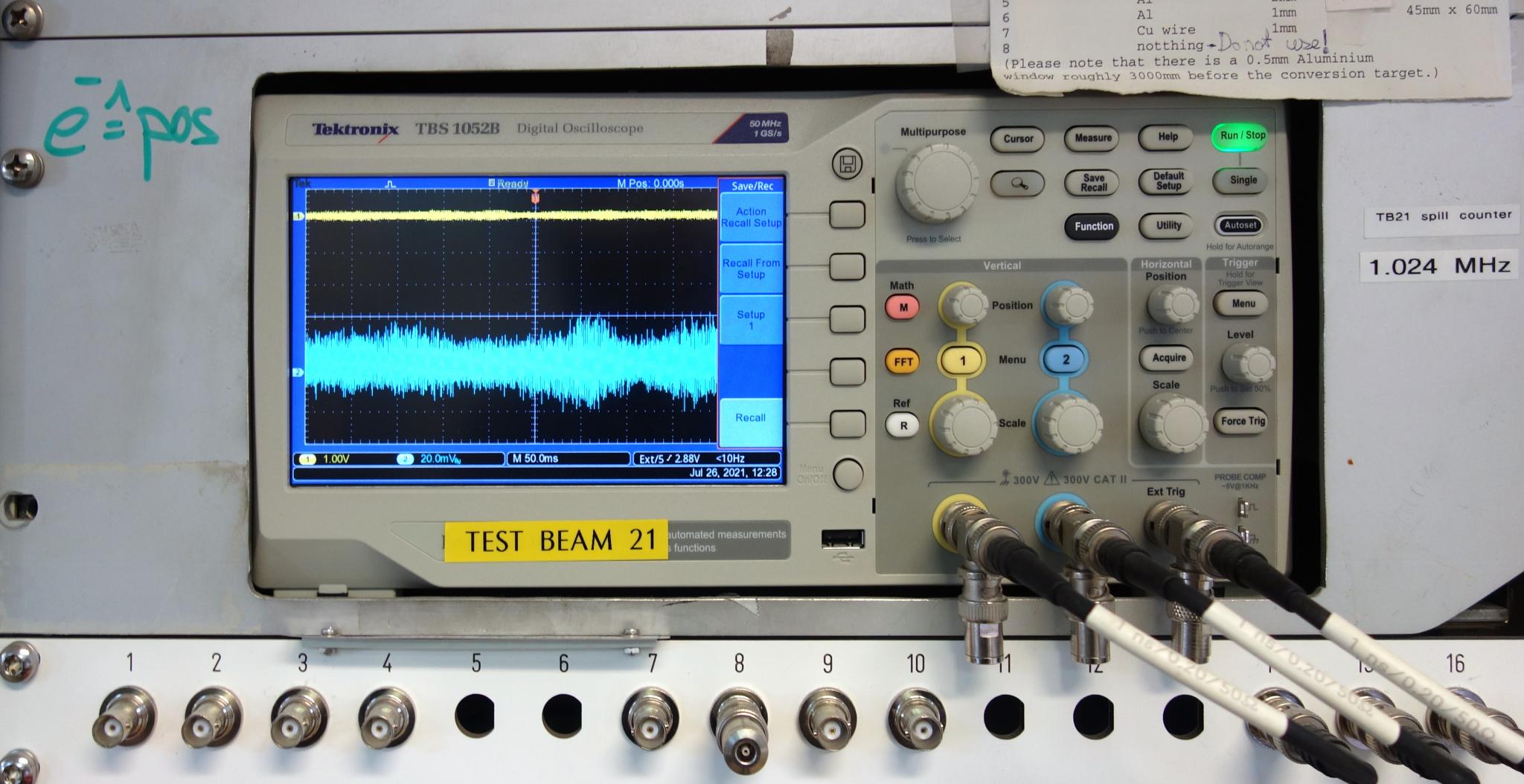
Beam-Signal Oscilloscope
An beam-signal oscilloscope can be found in addition for each beam line in the test beam huts . it shows the beam current and the converter spill signal that is produced by a photo multiplier with scintillator close to each converter target. Therefore, it picks up a signal, if the photon beam hits the target.
This allows deciding, if a "missing beam" problem is caused by the synchrotron and the fibre target, which is under control of the main control room or by the magnets, the converter, the collimators, the beam shutter or something else which should be under your control